Full-stack embedded systems project — from system architecture and schematic capture through 4-layer PCB layout and firmware bring-up. Demonstrates end-to-end capability across hardware design, power systems, USB protocol, and BLE wireless communication.
The brief was to create a device that removes cable dependency from USB MIDI controllers in a live or studio environment — bridging a standard USB MIDI keyboard into a wireless BLE MIDI stream receivable by any BLE-capable DAW host, including macOS with Apple's BLE MIDI specification.
The hard constraint was that the device could not be software-only. The target users don't want driver installations or middleware — the device must present as a native MIDI port with zero configuration overhead. Equally, for wired-preference scenarios or when battery is low, the same hardware needed to route keyboard data through to a host Mac directly, without the ESP32 in the path.
That passthrough requirement — true hardware-level USB signal routing that bypasses the MCU entirely — was the primary design driver. It ruled out simpler MCU bridging approaches and required a dedicated high-speed USB switch IC in the signal path, which in turn constrained the PCB layer stack, impedance planning, and power architecture.
Battery management added further complexity: the system needed to accept USB-C charge input while simultaneously providing a boosted 5V VBUS rail to power the connected keyboard — requiring a 3-rail power architecture with autonomous source switching.
The TS3USB30E high-speed USB 2.0 switch is the architectural pivot. In wireless mode it routes keyboard data lines to the ESP32's USB OTG peripheral. In passthrough mode it connects the keyboard port directly to the upstream USB-C connector, keeping the ESP32 entirely off the signal path — critical for signal integrity and for presenting a standard USB device to the host.
On the firmware side, the ESP32 runs the ESP-IDF native USB host stack to enumerate the keyboard as a USB HID/MIDI class device, extract MIDI data from USB bulk transfers, and re-emit it as BLE MIDI packets over NimBLE. The BLE MIDI implementation follows Apple's specification for service/characteristic UUIDs and packet timestamping, which is what allows macOS to surface it natively in Audio MIDI Setup without any driver.
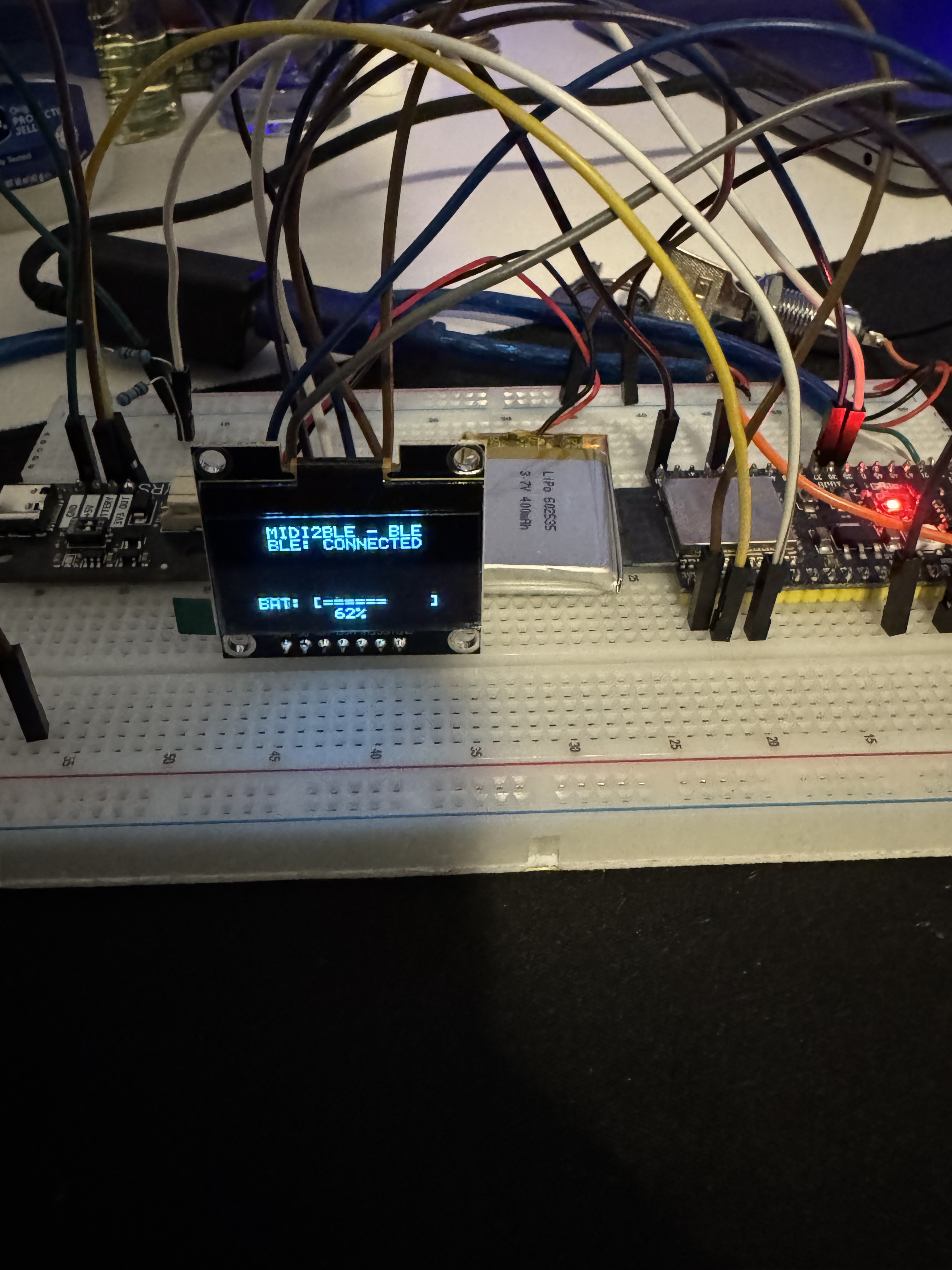
An SPI OLED provides live status feedback — connection state, mode selection, battery level — without host software dependency.
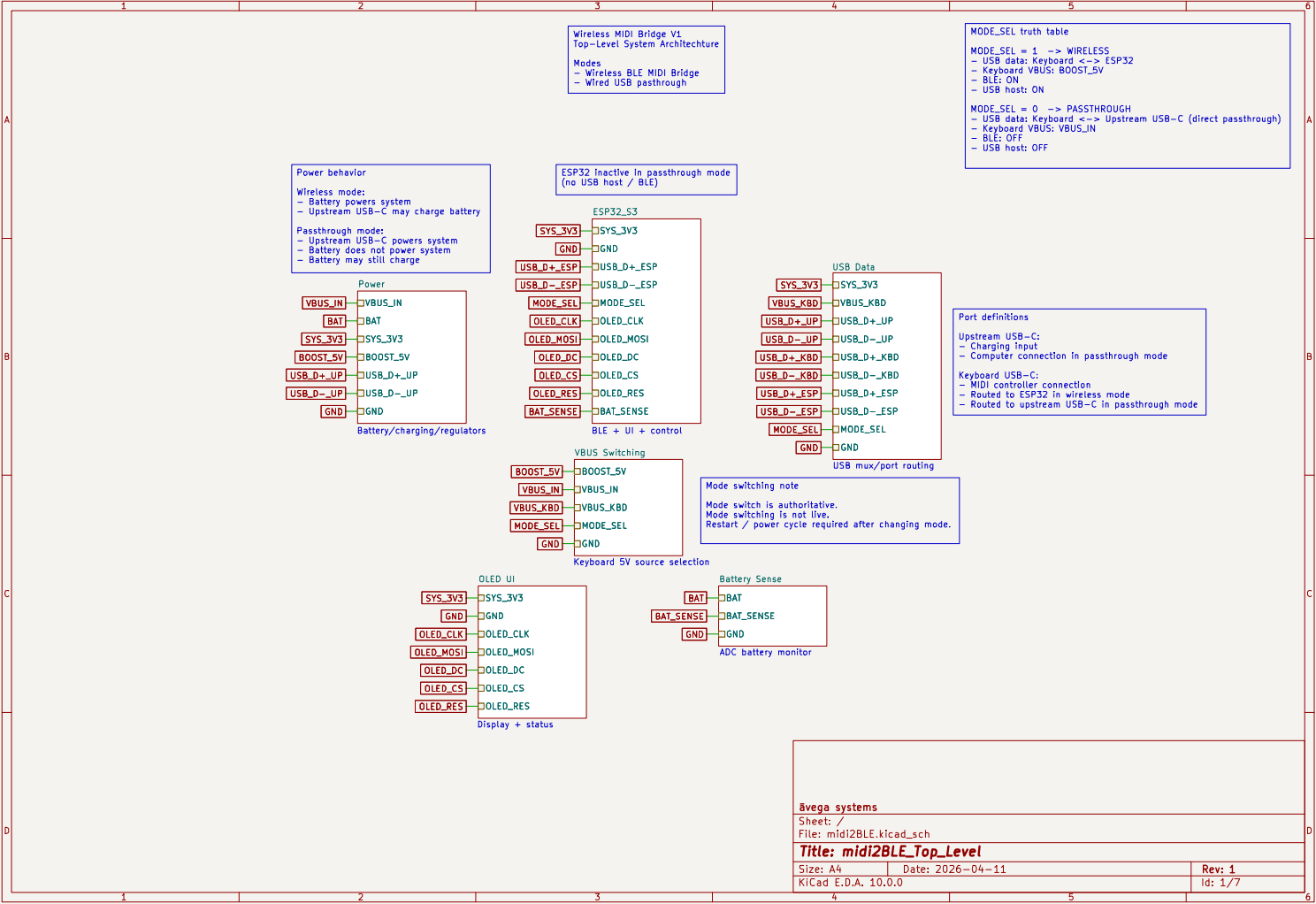
The power architecture manages three distinct rails with different source priorities, and does so transparently — the device can charge its LiPo battery from USB-C while simultaneously running off that USB-C input and supplying boosted 5V to the keyboard VBUS, all without interruption when the source switches.
The TPS2116 dual-input power mux provides seamless priority switching between USB-C VBUS and battery. When USB-C is present it supplies the system rail directly; on disconnect, the mux transfers to battery without a glitch on the output. The BQ24074 LiPo charger handles charge termination and battery protection, and operates in parallel with the mux so the battery charges whenever USB-C is present regardless of system load.
The 5V keyboard VBUS boost (TLV61047) runs from the system rail and is enabled only in wireless mode — in passthrough mode VBUS is sourced from the upstream USB-C connector, so the boost is disabled to avoid backfeeding the source.
| Rail | IC | Topology | Purpose |
|---|---|---|---|
| VSYS | TPS2116DRL | Dual-input mux | USB-C / LiPo priority switching, system rail |
| 3.3V | TPS62162DSG | Synchronous buck | MCU, BLE radio, USB switch, OLED, peripherals |
| 5V VBUS | TLV61047DDC | Boost converter | Keyboard VBUS supply (wireless mode only) |
| VBAT | BQ24074RGTT | LiPo charger | Battery charge management, protection, fuel gauge |
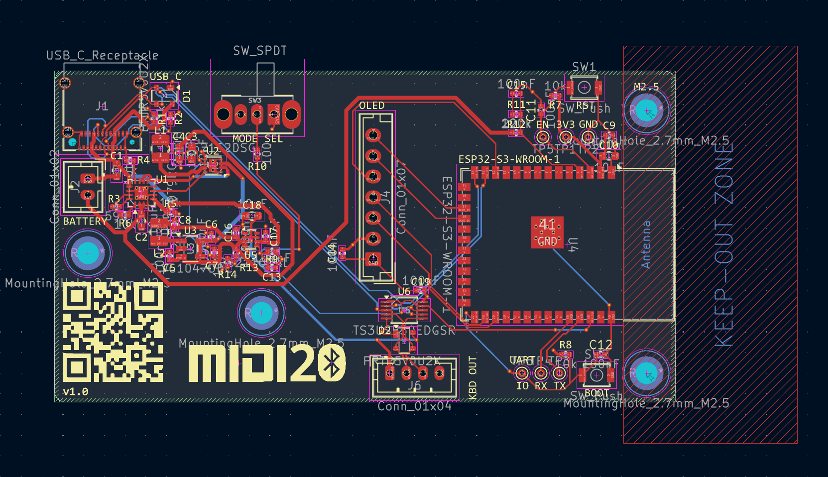
The 4-layer stackup was chosen primarily to achieve a solid, uninterrupted GND reference plane beneath the USB signal traces. USB 2.0 differential pairs (D+/D−) on the ESP32 peripheral, the USB switch, and the upstream USB-C connector all require controlled 90Ω differential impedance — achievable at the outer copper weight and dielectric on a standard JLCPCB FR4 stackup only when a solid reference plane is immediately adjacent.
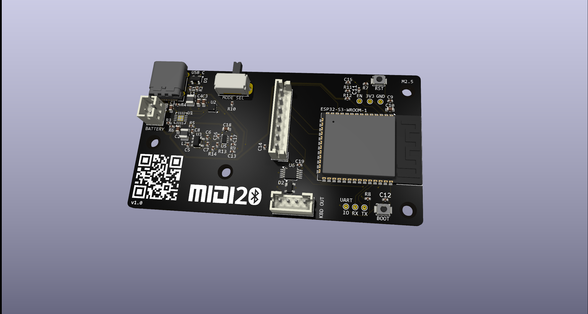
The layer assignment is: F.Cu (signal/component side), In1.Cu (GND plane), In2.Cu (3.3V power plane), B.Cu (secondary signal/routing). Power plane stitching vias are placed around the BQ24074 and TPS2116 thermal pads for both heat sinking and current distribution. The MCU antenna keep-out zone is maintained on all copper layers beneath the ESP32-S3-WROOM module's antenna section.
The TS3USB30E USB switch is centrally located between the keyboard-side USB-A port and the ESP32 USB OTG pins, minimising stub length on the signal switch outputs. The BLE antenna zone at the ESP32 module edge is kept clear of pours and vias on the adjacent inner layer.
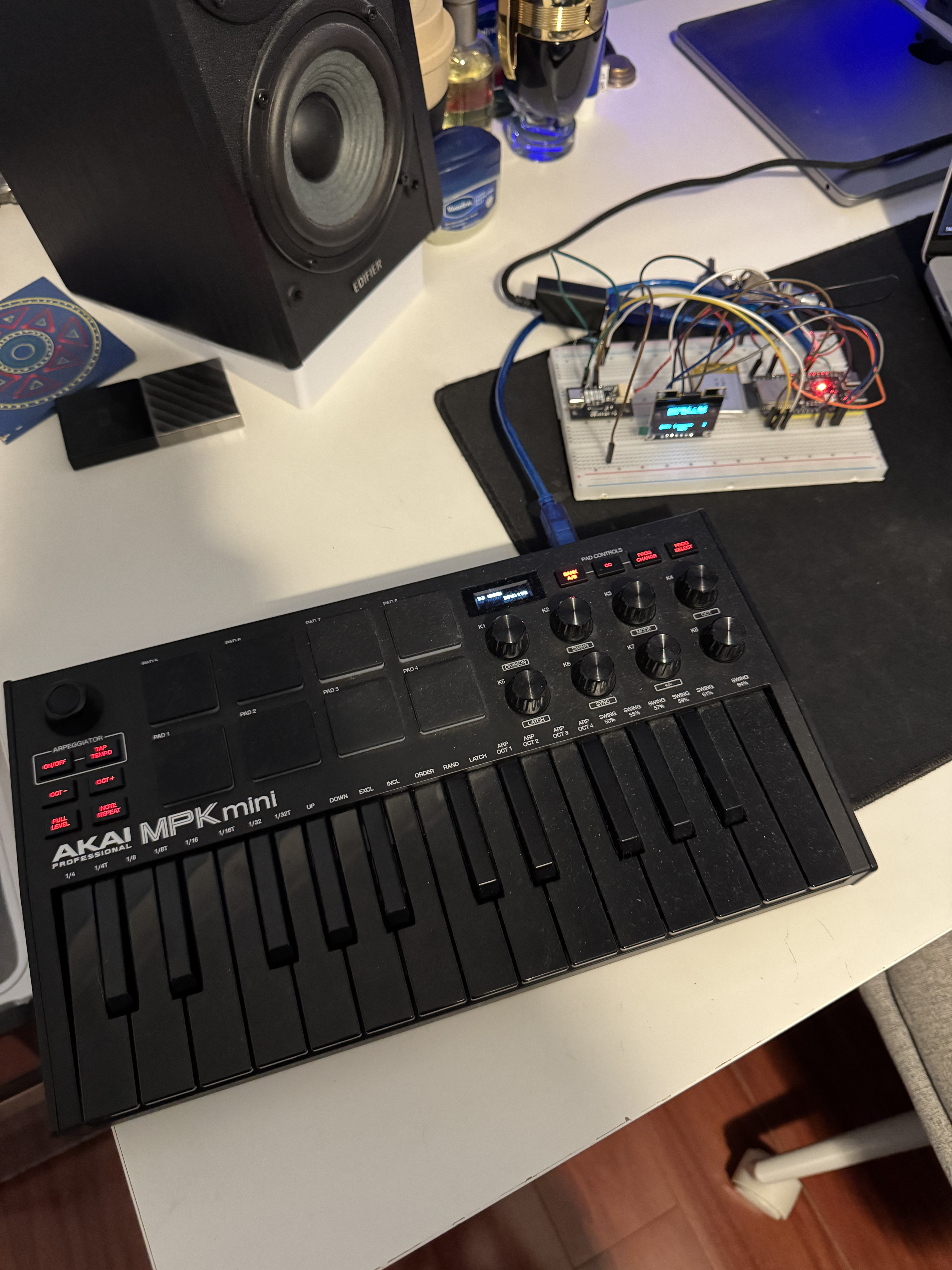
The end-to-end pipeline was validated on bench prior to PCB fabrication. A breadboard prototype with the ESP32-S3 dev kit running the complete firmware stack was used to verify USB host enumeration, MIDI parsing, BLE advertisement, and BLE MIDI packet delivery to a macOS host.
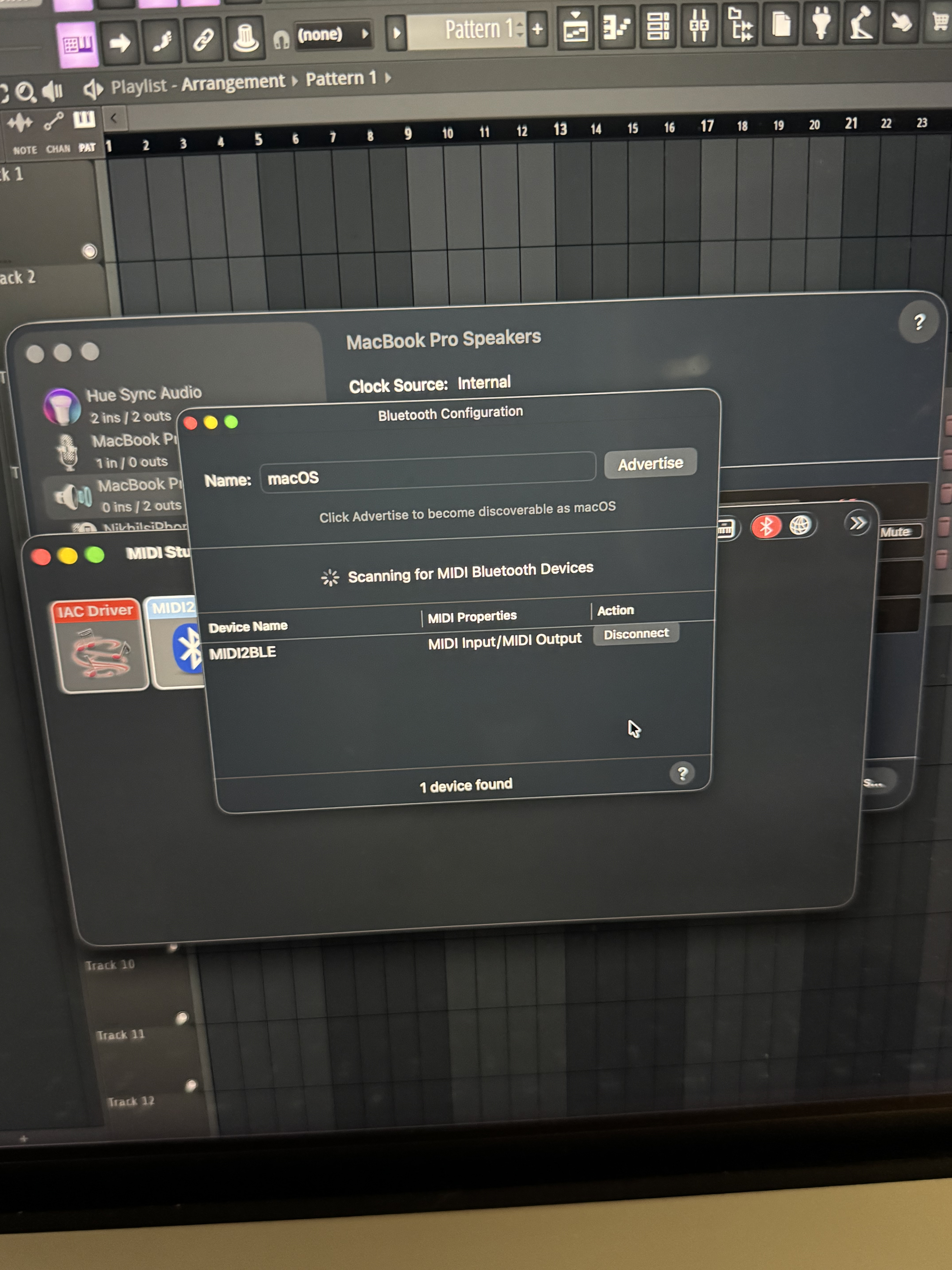
The keyboard was correctly enumerated by the USB host stack and MIDI events were received over BLE in FL Studio without any driver installation — the device appeared natively in macOS Audio MIDI Setup as a standard MIDI port, confirming Apple BLE MIDI specification compliance.
With firmware and PCB layout both complete, the project is at the point of fabrication submission. The 3D-printed enclosure is in progress, designed to mate with the PCB mounting pattern and expose the USB-A keyboard port, USB-C charge/passthrough port, mode toggle, and status OLED.
This project demonstrates Āvega Systems' approach to full-stack embedded hardware — system architecture, custom electronics, firmware, and validation in one tightly integrated engagement. If your team needs this kind of capability, get in touch.